 The principle of operation of devices for separating alcohol from other substances is subject to the law of physics, according to which when two liquids are boiled, their vapors contain
Distillation of the wort
The principle of operation of devices for separating alcohol from other substances is subject to the law of physics, according to which when two liquids are boiled, their vapors contain more vapors of the liquid whose boiling point is lower. Since the boiling point of alcohol is 78.3°C, and water is 100°C, when the water-alcohol solution boils, the vapors contain more alcohol than water. When boiling, water-alcohol vapors with a content of 51.6% alcohol are released from the brew with an alcohol content of 10%. If you evaporate 1/3 of the brew and collect the condensate, you get a water-alcohol liquid with a strength of about 33%.
You can increase the strength of the extracted alcohol by subsequent distillations. With an increase in the strength of the alcohol extracted from the brew with a content of 10% alcohol, several distillations are performed: the first distillation gives a distillate with an alcohol content of 37.7%, the second — 58.3%, the third — 77.8%, the fourth — 83%, the fifth — 87.3%.
Alcohol from the brew is isolated on a braga-distilling device, while all volatile impurities are driven away together with alcohol. The distillate obtained during distillation is called raw alcohol, and the remainder, which contains all suspended particles — is called distillery dreg.
Raw alcohol is a transparent colorless liquid with a strength of at least 88% by volume, the content of accompanying alcohol products, not more than: aldehydes-0.03-0.05%, esters-500-700 cm3 in 1 liter of anhydrous alcohol; methyl alcohol 0-0. 13% by volume. The distillery dreg contains from 4 to 9.5% of dry substances consisting of non-fermentable particles of raw materials and yeast.
The distillation apparatus consists of a column, a dephlegmator and a refrigerator. The mash column is a vertical cylinder with a diameter of 600-2000 mm, divided by shaped partitions, called plates, into separate parts, the distance between which is 180-500 mm, depending on the performance. In the middle of the plate there is a hole with curved up edges for the passage of steam (Figure 1). Above the hole is a cap. On the periphery of the plate there is a glass for draining the brew onto the underlying plate. This is a simple single-pack plate of single welding (Figure 1, a); a more efficient double welding plate (Figure 1, b).
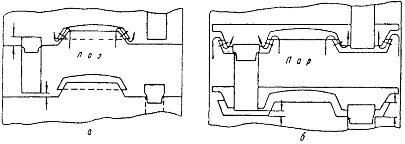
1 — Schematic of the distillation plates
The mash column consists of two parts: the lower — mash, or draining, where alcohol is evaporated from the mash, and the upper-alcohol, or strengthening, where alcohol vapors are strengthened by repeated boiling (Figure 2). The columns are mounted one on top of the other. However, there are two-column apparatuses, the alcohol part of which is made in the form of a separate column. The dephlegmator is a tubular heat exchanger, through the pipes of which the brew passes, and alcohol vapors enter the inter-tube space from the upper part of the alcohol column. To increase cooling, which helps to strengthen the alcohol more, cold water is supplied to the upper tubes of the dephlegmator. Due to the vapors, the brew is heated, and the alcohol vapors are cooled and flow into the column in the form of condensate. The strongest non-condensed vapors enter the refrigerator. The refrigerator is tubular, where cold water passes through the pipes, and in the inter — tube space-alcohol vapors. In most cases, refrigerators are made combined-half of the shell-and-tube type, and the second half consists of a coil placed in a vessel with water.
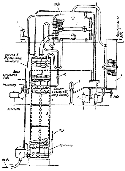
Figure 2-Diagram of a single-column distillation apparatus
Currently, continuous distillation apparatus are used.
The mash from the fermentation tank or from the intermediate tank is pumped to the dephlegmator 3, from there in a heated state it enters the upper plate of the mash column B. The work of the mash column proceeds in this way: the mash continuously enters the upper plate, steam is supplied from below, which, passing through the layers of mash on the plates, heats the mash to a boil.
When boiling, water and alcohol vapors are released. The brew, from which part of the alcohol is extracted, flows down to the second plate, where it is again brought to a boil by steam passing from below. The alcohol concentration in the brew decreases. When the brew passes the bottom plate, it is completely free of alcohol. 14-16 plates are installed in the column. For continuous output of distillery dreg from the brew column, a float-type bard regulator 2 is installed, from which the distillery dreg enters the collection and is pumped to the distillery dreg distribution station or to the feed yeast shop.
During normal operation of the device, the alcohol content in the bard is 0.015 %, which is a loss equal to 0.2% of the fermented substances in the brew. The loss of alcohol in the distillery dreg is systematically monitored.
Water-alcohol vapors with a strength of about 50% vol. from the top plate of the brew column rise to the alcohol A. The process of boiling in an alcohol column is similar, but there heat exchange occurs between the vapors coming from below and the phlegm returning from the deflegmator 3. In the alcohol column, repeated distillation is performed on each plate, which consistently increases the strength of water-alcohol vapors. The alcohol column consists of 8-10 plates. From the upper plate, the vapors enter the dephlegmator, where they are finally strengthened to the standard strength of raw alcohol. Phlegm flows down to the top plate of the alcohol column. The non-condensed vapors enter the refrigerator 4, where they condense to form raw alcohol.
To reduce the loss of alcohol from evaporation in the refrigerator, it is cooled to 15-20°C . From the refrigerator, raw alcohol through the filter 8 and the viewing lamp 9, where the jet size and temperature are observed, enters the control shell, which takes into account the amount of alcohol and then into the alcohol receiving compartment, from where it is pumped to the alcohol storage.
Steam enters the column through the steam regulator. To control the alcohol content in the bard, a test refrigerator is installed, in which steam is taken from the bard regulator 2 to the test lamp 5, where it condenses and enters the collection 6. In order to avoid the formation of a vacuum, which can lead to crumpling of the column, a vacuum interrupter 7 is installed in the lower and upper parts of the column. To observe the movement of the mash entering the column, an observation lamp 10 is located on the pipe. The steam consumption, depending on the design of the brew machine and the strength of the brew, is 17-25 kg per 100 kg of brew.
Rectification of alcohol
All chemicals obtained as a result of the distillation of mash, which are part of the raw alcohol, can be divided into four groups: aldehydes, esters, acids and higher alcohols.
Aldehydes are formed during fermentation, as well as during the oxidation of alcohols. The boiling point of aldehydes is significantly lower than that of ethyl alcohol. Acids are formed during fermentation, especially in infected brew. Only volatile acids (acetic and butyric) are distilled with alcohol. When acids combine with alcohol, esters are formed — very volatile compounds whose boiling point is also lower than the boiling point of alcohol. Higher alcohols are formed from nitrogenous substances-amino acids consumed by yeast for its nutrition. Higher alcohols are called fusel alcohols, they are the main components of fusel oil. Their boiling point is much higher than the boiling point of ethyl alcohol.
Impurities from raw alcohol are released by repeated distillation of it-rectification. The alcohol purified from impurities is called rectified ethyl alcohol and comes in three grades-first, highest purity and extra.
The task of rectification is to achieve a minimum content of impurities in the rectified alcohol and its high tasting qualities.
Physical and chemical basis of rectification
The rectification process is based on the same regularities as the distillation of mash. Liquids whose boiling point is lower than alcohol are distilled faster and with a higher boiling point — slower than alcohol. The ratio of the impurity content in alcohol vapors to its content in an alcohol liquid is called the rectification coefficient. For impurities more volatile than alcohol, the rectification coefficient is greater than one, and vice versa. When boiling the mixture, first of all, light-boiling liquids will evaporate, and then more difficult-boiling ones. The process is complicated by the fact that the rectification coefficient can vary depending on the strength of the alcohol.
If the raw alcohol is heated in a vessel, then the vapors will contain all the substances that are in the alcohol, but their mutual ratio will be different. The content of impurities in the vapors, the rectification coefficient of which is greater than one, will be greater than in the liquid. On the contrary, the content of impurities in the vapors, the rectification coefficient of which is less than one, will be less than in the liquid. If you put a poppet column over the vessel, then on each plate the vapors will condense and evaporate again, after each plate the vapors will become more and more enriched with impurities whose coefficient is greater than one, and impurities with a rectification coefficient less than one will become less and less. If the number of plates in the column is sufficient, then it is possible to achieve such a position that light-boiling impurities will gather at the top of the column, pure ethyl alcohol will be in the middle of the column, and hard-boiling impurities will be concentrated at the bottom of the column. Then, continuing the distillation process further, you can collect separately easy-boiling liquids, these will be aldehydes and esters, or head straps, then pure alcohol and, finally, hard-boiling impurities or tail straps, most of which are fusel oils.
Production of rectified alcohol of the first grade and alcohol of the highest purity
For rectification of raw alcohol, devices of the following systems are used: batch-single-column; continuous — two, three and four-column; continuously operating, in which the braga-distilling and rectification devices are combined.
Currently, the majority of distilleries equipped with continuously operating distillation and rectification apparatus.
The simplest type of rectification devices are periodic devices. The apparatus (Figure 3) consists of a cube 1 with tubular heating elements 2, a distillation column 3, a dephlegmator 4, a refrigerator 5, and an alcohol lamp 6. The raw alcohol poured into the cube is heated by steam. In addition to the heating elements, a bubbler for entering open steam into the cube is also installed in the cube for blind heating.
To ensure constant pressure in the column, a steam regulator is installed on the steam line. The distillation column can be equipped with mesh or cap plates in an amount of at least 40 pieces.
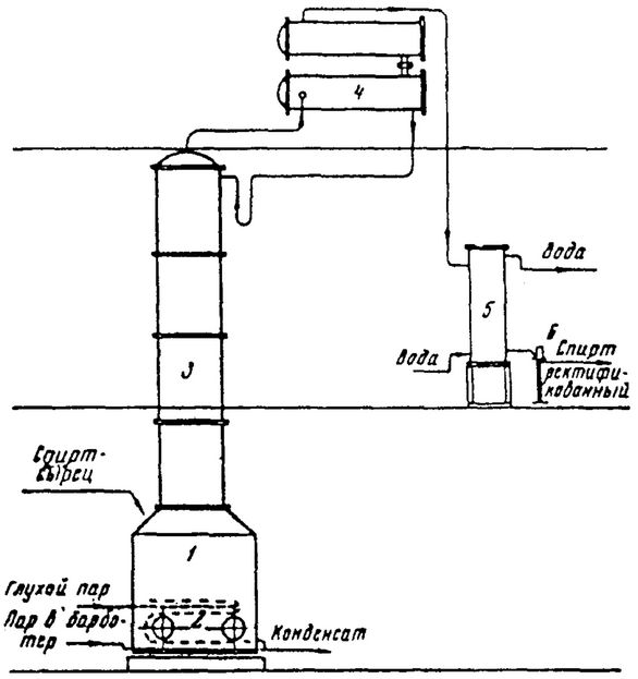
Figure 3-Scheme of periodically operating rectification apparatus
Obtaining rectified alcohol of I grade
A certain volume of raw alcohol, called bulk, is loaded into the cube. Without waiting for the cube to fill, as soon as the alcohol covers the bubbler and coils, steam is fed through them. Due to vigorous mixing with hot steam, the heating of the bulk is intense and after 0.5-1 h after filling the cube, the column begins to warm up. The bulk is brought to a boil, alcohol vapors rise along the column and enter the dephlegmator.
After heating, the columns are fed water to the refrigerator and the dephlegmator so that the alcohol vapors completely condense in the dephlegmator and do not get into the refrigerator (as in the production of cognac and fruit alcohols). Then the water supply is reduced so that the vapors of alcohol (low-boiling components), i.e. esters and aldehydes, pass into the refrigerator, where they condense and, cooling, leave the apparatus. They are selected in a separate container in the amount of 0.5 % of the volume of raw alcohol in the cube. The ether aldehyde fraction is a liquid with a sharp smell and a greenish color. Then 2.5-5% of the colorless product is selected — the III-th initial grade. After that, 4-8% of alcohol of the II-th initial grade, drained separately, is selected. At the end of its selection, the quality is checked for purity with sulfuric acid. If it corresponds to the quality of rectified alcohol of the 1st grade, the selection is carried out with the maximum possible speed, maintaining the necessary strength. It is taken away by 85% of the bulk volume. After that, the selection of alcohol of the second final grade begins. When the strength is reduced to 85-80%, the selection of the second final grade is stopped and the fraction with fusel alcohols is separately selected, which is processed and washed in a fusel separator.
The second grades are added to the next bulk, which increases the yield of rectified alcohol of the 1st grade to 95-97 %; the ether aldehyde fraction is 2.5-3.5%, fusel oil-0.3-0.4 % and about 1% is lost.
The distillation is completed at a distillate strength of 2% in the lantern, at which point the alcohol content in the cube is almost zero. At the end of the distillation, the steam supply to the cube is stopped, and the remaining liquid is drained into the sewer.
The method noted above is called the single strong bulk method. It makes it possible to obtain alcohol of the highest quality. More economical is the method of complex strong bulk. It consists in the fact that after removing approximately 85-90% of the alcohol content in the bulk, the distillation is stopped for a short period, the cube is re-filled with raw alcohol and rectification begins in the usual way. Thus, the cube is filled several times until the incoming alcohol is too diluted with residues from the previous distillation and the content of fusel oil in the cube does not become too high. With six fillings of the cube, the strength of the last bulk would be about 60%, the content of fusel oil about 3 %.
Therefore, in practice, no more than three bulk loads are made. The three-syllable bulk method allows you to increase the selection of rectified alcohol, get more concentrated ether aldehyde fraction and fusel oil and reduce steam consumption compared to a single bulk.
Obtaining rectified alcohol of the highest purity
Rectified alcohol of the highest purity on a batch device can be obtained from raw alcohol by double rectification or delayed distillation methods.
To obtain rectified alcohol of the highest purity by double rectification, the bulk (filling the cube) is produced with rectified alcohol of the 1st grade. Alcoholic products from the previous distillation are not allowed to be used. Distillation begins with an hour delay (water supply to the dephlegmator so that all alcohol vapors condense in the dephlegmator without leaving them in the refrigerator) to concentrate the head impurities on the upper plates of the column. After the delay, the initial grades are selected, then the rectified alcohol of the 1st grade. When the quality of alcohol corresponds to the quality of the highest purification, which is determined by analysis, it is selected in an amount of 50-60% of the bulk volume. The end of the selection of alcohol of the highest purity is determined by the analysis of the content of fusel oil.
When conducting complex bulk loads, the next bulk is started after the selection of rectified alcohol of the highest purity.
When rectified high-purity alcohol is obtained by slow distillation from raw alcohol, a number of delays are carried out during distillation: before the selection of the ether aldehyde fraction (1.5 h), before the selection of the high-purity variety (1 h) and before the end of its selection (0.5 h). The moments of transition to the selection of varieties are determined by the results of analyses. With slow distillation, 60-65% of rectified alcohol of the highest purity is obtained from the absolute alcohol content in the bulk.
Obtaining rectified alcohol on continuously operating machines
More progressive are continuously operating rectification devices. The principle of operation of the device is that the raw alcohol is consistently released from impurities in accordance with the value of the evaporation coefficients, depending on the strength of the alcohol. To create zones of separation of impurities, the device consists of two or more columns, each operating in its own mode. The yield of rectified alcohol is high (92.5-94%); concentrated head and tail products, lower alcohols do not require repeated distillation, which saves steam. Maintenance of the device is much easier, since processing of intermediate products is excluded. The device lends itself to automatic control, which is carried out in a number of factories.
The simplest is a two-column apparatus (Figure 4), consisting of two columns: epyuratsionnoy 1 and rectification 2.
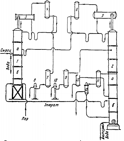
Figure 4-Diagram of a two-column distillation apparatus
The epuretion column
The epuretion column is designed to separate head impurities from the raw material and in turn consists of the lower boiled part b and the upper aldehyde part a. The column is equipped with a dephlegmator 3 and a condenser 4. Raw alcohol flows continuously to the upper plate of the boiled column and, together with the phlegm flowing from the aldehyde column, goes down the plates of the boiled column. In the lower part of it is fed heating steam, moving up and entrapping the head impurities.
Boiled plates are set so much that when the raw alcohol moves through them, the head impurities have time to evaporate, usually 15-20 plates. The water-alcohol solution, freed from most of the head impurities, is called epyrate, and therefore the column is called epyration. In epurate should contain not more than 0.0005% aldehydes and not more than 100 mg/l of esters. Tail impurities are retained in the epuration column, because on its plates there is a liquid with a high concentration of ethyl alcohol, at which the evaporation coefficients of the tail fractions are less than one (the content of these impurities in the vapors is less than in the liquid). The amount of ether aldehyde fraction taken from the upper column does not exceed 3% of the processed raw material, its strength is 95-96.5%.
From epuration column is released from the head of impurities, epurate is sent to distillation column 2. At the point of receipt of the epuret, the column is divided into two parts: the upper, a — concentration and lower b — boiled.
Distillation column is designed to separate from epurate pure rectified alcohol. The epurate contains a small amount of head impurities, and in addition, ether formation occurs in the column itself, partial oxidation of alcohols into aldehydes, so that these head impurities must also be isolated in the distillation column.
Impurities rise in the dephlegmator 5 and condenser 6, their vapors, condensing, form the so-called unpasteurized (non-standard) alcohol, which is returned to the epuration column for recycling. The amount of it is 2%. Standard rectified alcohol is taken as a liquid from the 4th-6th upper plate of the rectification column and enters the refrigerator and then through the lamp and the control shell into the alcohol receiver.
Intermediate and residual impurities entering into the distillation column with epurate, are concentrated in the lower part boiling column. Fusel oil is taken from the steam space of one or more lower plates and sent to the refrigerator and through the lamp to the oil separator. Fusel alcohol is selected slightly above the concentration zone of fusel oil.
Obtaining rectified spirit on distillation and rectification devices
Rectified alcohol is obtained recently directly from the mash for the distillation and rectification apparatus. These devices are divided into: direct-acting, semi-direct-acting, indirect-acting and dual-flow devices.
The devices of direct action. In direct-acting devices (Figure 5), the head impurities are separated directly from the mash in an epuretion column mounted on the mash column. Due to the low concentration of alcohol in the brew, the evaporation coefficients of impurities are large and the epuration proceeds fully. After that, the mash, devoid of head impurities, enters the mash column 3, where ethyl alcohol, tail impurities and residues of head impurities are evaporated from it. The main mass of vapors from the brew column is sent to the distillation column 5. A small part of the vapor passes into the epuretion column 1 for its heating.
In this type of apparatus, the distillation column receives vapors that have already been released from the bulk of the head impurities.
Tail and intermediate products, as well as residues of head products, are collected in a distillation column. The rectified alcohol in liquid form is removed from one of the upper plates of the rectification column.
Direct-acting devices are the most economical in terms of heat engineering, but the taste and smell of alcohol on them are bad. The carbon dioxide contained in the mash, released in the mash column, brings into the distillation column a pair of fusel oils. Penetrating into the area of pasteurized alcohol, these vapors give the rectification an unpleasant smell.
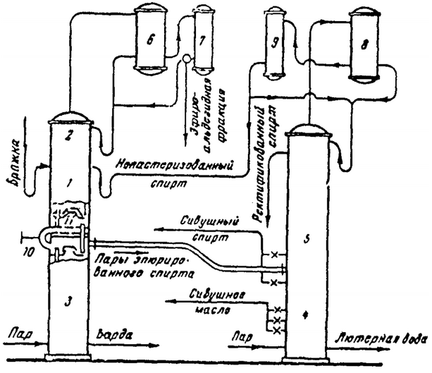
Figure 5 — diagram of a distillation and rectification apparatus of direct action
Semi-direct action devices
In devices of this type (Figure 6), the mash is not subjected to preliminary epuration. It enters the brew column 1, where vapors containing all impurities, alcohol and water are released.
These vapors enter the middle part of the epuration column (the lower part of this column 2 is evaporated, and the upper part 3 is concentrated) through the trap 9 separating the suspended particles, where they are subjected to epuration.
The alcohol purified from head impurities, which contains head and intermediate impurities, enters in liquid form into the distillation column 6, equipped with a dephlegmator 7 and a condenser 8.
Such a scheme is less economical in terms of heat, but it makes it possible to obtain high-quality rectified alcohol.
The scheme of a three-column semi-direct rectification apparatus, formed as if from a brew column and a two-column rectification apparatus, is most common in factories.
The mash without preliminary epuration enters the mash column 1. Vapors from the mash column through the trap 9 enter the middle part of the plotting column. The lower part 2 of this column is boiled, the upper part 3 is concentrated. The dephlegmator 4 condenses the bulk of the vapors and the condensate returns to the column in the form of phlegm. The vapors not condensed in the dephlegmator, containing head impurities, enter the condenser 5, from where they are partially directed to the refrigerator and the lamp, and partially return to the column 3.
The liquid epuret, freed from the head impurities, is sent to the distillation column 6, equipped with a dephlegmator 7 and a condenser 8. Pasteurized alcohol is taken from the upper (fourth-sixth) plates of the distillation column. Intermediate products and fusel oil are selected in the same way as in a two-column distillation apparatus.
The head products, i.e. unpasteurized alcohol, which have passed the dephlegmator 7, enter the condenser 8 in the form of vapors, from where they are returned partially to the distillation column on the upper plate, and partially sent to the epuration column 3.
Heating steam enters the brew and distillation columns through steam regulators. In epuration column, steam is supplied from boiling column. The brew entering the device is preheated in the dephlegmator.
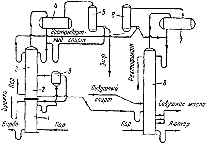
Figure 6 — diagram of a distillation and rectification apparatus of the semi-direct action
Devices of indirect action
Devices of this type are a combination of two devices: one of them gives raw alcohol, and the second produces its rectification. On such devices, high-quality alcohol is obtained, and they are accepted as standard for the production of alcohol of the highest purity.
The mash is pumped into the heater 2 (Figure 7), where it is heated by water-alcohol vapors coming from the mash column 1. The vapors pass through trap 10, where liquid particles are separated. The heated mash enters the separator 11, in which carbon dioxide and non-condensed gases are released from it. The gases flow through the condenser 3‘ into the alcohol trap, and the brew is sent to the brew column 1. Condensate of water-alcohol vapors from the condenser 3 and 3', the brew heater 2 and the alcohol trap are sent to the epuration column 4. This column is equipped with a dephlegmator 5 and a condenser 6.
Head products from the condenser 6 enter through the refrigerator and rotameter into the lamp 15. The water-alcohol solution (epyrate) released from the main part of the head impurities is sent to the distillation column 7. This column is equipped with a dephlegmator 8 and a condenser 9. From the condenser 9, alcohol and head products (unpasteurized or non-standard alcohol) are selected. Unpasteurized alcohol in the amount of 3% of the absolute alcohol introduced into the column is returned to the epuration column. The rectification is taken in liquid form from the third, fourth, sixth and seventh plates (counting from above) of the rectification column and enters the refrigerator 13, from where it is sent through the rotameter to the lantern 15.
Fusel oil enters the refrigerator 14 in the form of vapors, from which it is sent to the oil separator. The fusel oil extracted in it is sent to the storage; the alcohol-water liquid from the oil separator is returned to the distillation column.
In the rectification column, intermediate products (fusel alcohol) are also selected and sent to the refrigerator 12.
The columns are equipped with vacuum interrupters, test refrigerators for condensing vapors from residual water and distillery dreg for monitoring the alcohol content in them.
The supply of heating steam to the brew and distillation columns is regulated by steam regulators. In epuration a column of steam comes from extraction part of the rectifying column.
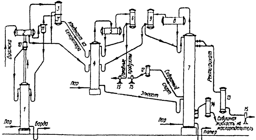
Figure 7 — diagram of a distillation and rectification apparatus, indirectя
Production of high-purity rectified alcohol
Upon receipt of the rectified spirit of the highest purification in the distillation and rectification apparatus is necessary to change the mode of work compared to getting ordinary rectified spirit. To do this, you need:
- 1. increase the selection of unpasteurized alcohol by 1.2-1.5 times. Return all unpasteurized alcohol to the epurate column;
- 2. make a selection from the distillation column, except for fusel oil, fusel alcohol;
- 3. reduce the performance of the device by 20-30%.
In order not to reduce the performance of existing devices when switching to the production of high-purity rectified alcohol, it is necessary to supplement the devices with a final cleaning column. In this column, the rectified alcohol is brought to the purity required by GOST for rectified alcohol of the highest purity.
Obtaining rectified spirit on distillation and rectification devices
VNIIFS employees together with employees of the Lipetsk distillery and Yproperty developed dual-flow distillation and rectification apparatus. The design of the device is based on the separate processing of two independent product streams, of which one, representing a mixture of ethyl alcohol and water, is processed according to the direct action scheme, and the second, containing all alcohol impurities, is processed according to the indirect action scheme.
The apparatus (figure 8) consists of industrial, epuration, the first and second distillation columns. The mash column consists of two parts: the lower-boiled and the upper-epuretion, which is designed to isolate impurities from the mash.
The mash pump 1 is fed to the mash heater 2, where it is heated by the heat of condensation of water-alcohol vapors of the first distillation column to 65-70°C. The heated mash through the carbon dioxide separator 3 enters the upper plate of the epuration part of the mash column 4. At a temperature of 90-95°C on the upper plate of the epuretion part of the mash column, the head, intermediate and tail impurities form azeotropic mixtures, which ensures the separation of almost all volatile impurities from the mash. The mash, freed from impurities, enters the boiled part. Water-alcohol vapors released from this brew, from the upper plate of the boiled part of the column in the amount of 85% through the foam trap 7 enter the first distillation column 15. The vapors released in the epuration part of the column, in an amount of 15%, enter the dephlegmator 8 and the condenser 9. The distillate obtained in the dephlegmator 8 and the condenser 9 is sent to the epuration column 12. Vapors from the column 12 enter the dephlegmator 13. The phlegm flows into the column, and the non-condensed vapors from the dephlegmator enter the condenser 14, where they are completely condensed. The ether-aldehyde fraction in the amount of 1-1.5% is taken from the condenser 14.
Epurate with a strength of 30% vol. from the column 12 in the case of processing of defective raw materials enters the second rectification column 17. From the upper plates of column 17, rectified alcohol of the highest purity is selected, from the lower plates-fusel oil and fusel alcohol, sent for washing. From rivers